

Determination on Inventive Step of a Mechanical Patent - Supreme Administrative Court Reversed the Judgment Of IP Court
Date:8 June 2023
【Volume 111】
Recently, Taiwan Supreme Administrative Court reversed the judgment of Taiwan Intellectual Property and Commercial Court (IPCC) about inventive step in a patent case (Supreme Administrative Court 2022 Shang Zi No. 366 Judgment) in the mechanical field. In mechanical patents, the scope defined by a rough description about the appearance, structure, mode of action of components in claims may be too broad to be distinguished from the prior art. When the prior art has disclosed similar components, even though the description in the specification and figures may show that the principle or force mode of the disputed patent is in fact different from that of the prior art, it is still hard to prove that what is claimed involves an inventive step compared to the prior art sometimes. Furthermore, if the specification does not disclose the effects that the technical features can reach specifically, it is very likely that the court will determine that as part of the technical features has been disclosed by the prior art and the invention of the prior art has the same function as that of the disputed patent, the disputed patent does not show any advance in effects, so the disputed patent is merely a simple change of the prior art. In follows, we will introduce and analyze this case in which Taiwan Supreme Administrative Court reversed the judgment of IPCC based on these reasons.
Case Facts
Wu, Shu Mu filed an invalidation action against the invention patent “SINGLE-NOZZLE TIRE VALVE AND DIRECT-PRESS DUAL-VALVE AUTOMATIC SWITCHING TIRE VALVE” (TWI560384, ‘384 patent) owned by BETO ENGINEERING AND MARKETING CO., LTD. (patentee). Upon examination, TIPO invalidated claims 1 to 4 with the reason that the claims 1 to 4 lack an inventive step, and the patentee therefore lodged an administrative appeal against the administrative act of TIPO. IPCC considered that the claim 3 of ‘384 patent involved an inventive step and vacated the decision of invalidating claim 3 in the original administrative act. (Taiwan Intellectual Property and Commercial Court 2021 Xing Zhuan Su Zi No. 31 Judgment) Wu then filed an appeal to Taiwan Supreme Administrative Court. In the end, Taiwan Supreme Administrative Court reversed the original judgment of IPCC, considered that the claim 3 of ‘384 patent lack an inventive step (Supreme Administrative Court 2022 Shang Zi No. 366 Judgment) and remanded the case to IPCC for a retrial.
The main issue in this case is whether Exhibit 2 has disclosed the technical feature “the outer surface of each holding paw is formed as an arched portion widening radially” in claim 3 of ‘384 patent.
The main technical features of ‘384 patent and the Exhibit
1. Technical features of ‘384 patent:
‘384 patent provides a single-nozzle tire valve and direct-press dual-valve automatic switching tire valve. The technical features in the claim 1 and the claim 3 include:
Claim 1: a single-nozzle tire valve comprising:
A: a body with a valve hole penetrating through it, wherein the body is connected to an air supply hole between the two ends of the valve hole and the top of the body is formed as a ring flange narrowing in a radial direction;
B: a valve plug placed in the body, wherein the valve plug is capable of moving reciprocally along the axis of the valve hole of the body between a first position and a second position in a position-limited manner; when the valve plug is at the outer ring surface near the top, the valve plug is formed as a ring shoulder part corresponding to the ring flange; and when the valve plug is above the ring shoulder part, the valve plug is formed as a pressing part with smaller diameter which can protrude out of the valve hole and a flow channel is formed inside the valve hole to communicate with the outer ring surface;
C: a ring pressing component combined to the bottom of the valve plug, wherein the ring pressing component is provided with a plurality of holding paws which are separated by contracting grooves and arranged in a circle to define a contracting hole which can contract radially and is arranged coaxially with the valve hole;
D: a ring-shaped first nozzle with a first nozzle hole to be inserted by a tire valve, wherein the first nozzle is placed in the contracting hole.
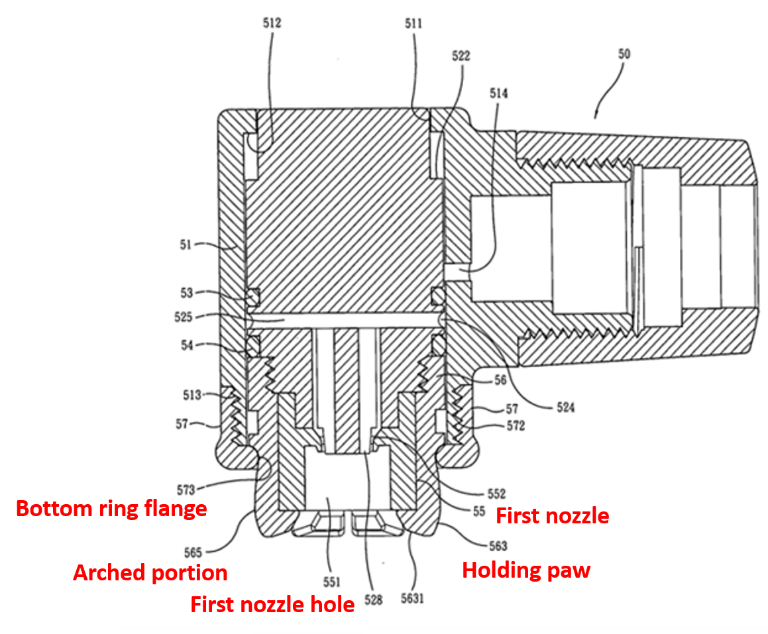
Claim 3: the single-nozzle tire valve in Claim 1, wherein the outer surface of each holding paw is formed as an arched portion widening radially.
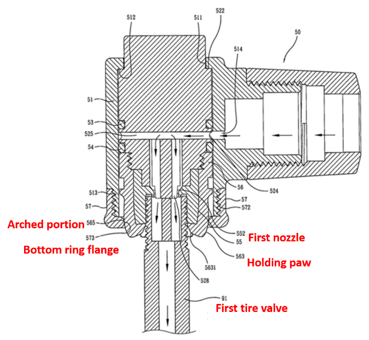
| Figure 7 of ‘384 patent (Before connecting the first tire valve 91) | Figure 8 of ‘384 patent (After connecting the first tire valve 91) |
|---|---|
 |
 |
2. Disclosure of Exhibit:
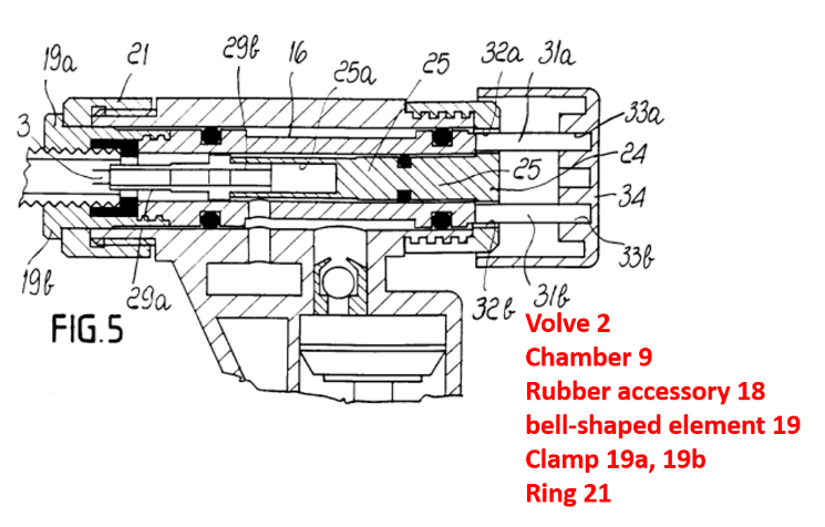
Line 9 to Line 18 in Page 3 of the specification of Exhibit 2 describes: “…safety valve is inserted into the bell-shaped element by hand and the end thereof presses on the bottom of rubber accessory 18 to enclose the front part; upon continuous pressing, the bell-shaped element will enter the chamber 9 gradually and intervene the opening which then pushing the clamp toward the center axis of the bell-shaped element to hold the safety valve tightly…”
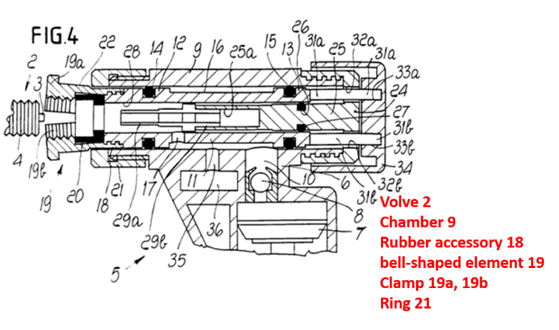
| Figure 4 of Exhibit 2 (disconnected from the valve) | Figure 5 of Exhibit 2 (connected with the valve) |
|---|---|
 |
 |
Opinion of Taiwan Intellectual Property and Commercial Court
IPCC determined that claim 3 of ‘384 patent, “the outer surface of each holding paw is formed as an arched portion widening radially,” cannot be easily made by simply changing Exhibit 2 and therefore involves an inventive step.
- TIPO and Wu both claimed that the “arched portion widening radially” of ‘384 patent corresponds to the bell-shaped element of Exhibit 2. However, Figure 4 of Exhibit 2 showed that the outer surface of the bell-shaped element is generally straight and there is an additional step-like flange protruding out at the bottom. The invention of Exhibit 2 does not have any structural feature corresponding to that of ‘384 patent.
- The figures and specification of ‘384 patent described that “enable the contracting hole to clamp the first nozzle radially tightly automatically by the guide of the arched portion of each holding paw”, “holding paw presses the nozzle ‘directly’ to change its shape radially for fastening the tire valve tightly and form a structure which can minimize gas leak during inflation”. Based on the description above, it can be known that the “arched portion widening radially” of ‘384 patent may be used for “guiding” to increase the effect of clamping the tire valve tightly. By contrast, Figure 5 of Exhibit 2 showed that there was a step-like flange protruding out at the bottom of bell-shaped element 19. However, the flange protruding out only serves the function of stopping rather than guiding and cannot increase the effect of clamping the tire valve tightly while, based on the problems to be solved described in the specification of ‘384 patent, its main aim is to solve the “problem of gas leak”. Based on the fact that they have different structural features, operations and effects, it is hard to concluded that the bell-shaped element of Exhibit 2 can be easily adjusted to form the “arched portion widening radially” of ‘384 patent to accomplish the invention of ‘384 patent by simply changing Exhibit 2.
Opinion of Taiwan Supreme Administrative Court
However, Taiwan Supreme Administrative Court considered that the issue whether the invention of ‘384 patent cannot be easily made by simply changing Exhibit 2 existed ambiguity. The reasons included:
- In the bell-shaped element 19 showed in Figure 4 of Exhibit 2, from right to left the end with minimum diameter is connected to sleeve 11, then connected to a clamping part with larger diameter by a slanted step part and is provided with a clamp protruding out in the end, which may show that the outer surface of the holding paw of bell-shaped element of Exhibit 2 widens radially.
- Page 3 of the specification of Exhibit 2 described that “…safety valve is inserted into the bell-shaped element by hand and the end thereof presses on the bottom of rubber accessory 18 to enclose the front part; upon continuous pressing, the bell-shaped element will enter the chamber 9 gradually and intervene the opening which then pushing the clamp toward the center axis of the bell-shaped element to hold the safety valve tightly…”. Also, Figure 4 of Exhibit 2 disclosed that there is space between the outer edge of rubber accessory and the inner edge of bell-shaped element and Figure 5 disclosed that the space disappears when the bell-shaped element is pressed, which may show that the rubber accessory would be restricted by the clamp of the bell-shaped element (pressed radially) and therefore could fasten and seal the valve.
- Accordingly, the bell-shaped element in Exhibit 2 may teach the arched portion. The bell-shaped element in Exhibit 2 has a step-like shape and will press this step when combined to the nozzle to clamp. Therefore, it may have the same operation and function as ‘384 patent. Also, specification of Exhibit 2 disclosed that the bell-shaped element may be replaced by another bell-shaped element with clamp in appropriate size.
- If Exhibit 2 has indeed disclosed the technical feature “the outer surface of each holding paw is formed as an arched portion widening radially” in the claim 3 of ‘384 patent and also has the same operation and function as ‘384 patent and the invention of ‘384 patent does not show advance in effects, the issue whether the invention of the claim 3 of ‘384 patent cannot be easily made by simply changing Exhibit 2 exists ambiguity.
Wisdom Suggested Strategies
According to our analysis, the force mode and guiding effect of the “arched portion widening radially” in the claim 3 of ‘384 patent is actually different from that of the bell-shaped element 19 in Exhibit 2. However, the rough description about the technical feature “an arched portion widening radially” in the specification and the claim 3 of ‘384 patent and the lack of advance in effects led to the different judgments of IPCC and Taiwan Supreme Administrative Court, where Taiwan Supreme Administrative Court considered that it is hard to prove the difference between the invention of ‘384 patent and the bell-shaped element 19 in Exhibit 2 and therefore the invention of ‘384 patent can be easily made by simply changing Exhibit 2.
In the “arched portion widening radially” in the claim 3 of ‘384 patent, the feature of widening radially means that the arched portion 565 of the holding paw 563 is pushed against by the flange of ring bottom 573 and bears force when the first tire valve 91 is inserted into the first nozzle hole 551 of the first nozzle 55, and therefore guides the contracting hole 561 to clamp the first nozzle 55 radially tightly automatically; and the first nozzle 55 is compressed and then clamps the first tire valve 91 tightly (referring to Figure 8 of ‘384 patent). By contrast, the bell-shaped element 19 in Exhibit 2 enters chamber 9 gradually when the inserting valve 2 enters and the clamp 19a, 19b are pushed toward the center axis, which can generate the effect of clamping tightly because the valve 2 presses against the bottom of the rubber accessory 18, rather than because the bell-shaped element 19 is applied with force. Furthermore, the flange protruding out at the bell-shaped element 19 can only stop clamp 19a, 19b at ring 21 (referring to Figure 5 of Exhibit 2) and cannot guide the clamp to contract. Accordingly, the bell-shaped element 19 of Exhibit 2 does not show the force mode and guiding effect of the “arched portion widening radially” in the claim 3 of ‘384 patent.
Accordingly, if there are more details defined specifically about the appearance and shape of the “arched portion widening radially” in the claim 3 of ‘384 patent to illustrate the effect of the shape of this arched portion on the configuration and structure of the nozzle 50 and the cooperating effect of the same for guiding the holding paw 563, and if there is description regarding the advantageous effects of this technical feature clearly in the specification to connect to the ability of the first nozzle 55 to clamp the first tire valve 91 tightly, then it may be claimed based on these descriptions that the technical feature of claim 3 can increase the ability to prevent gas leak, operates in a way different from the invention of Exhibit 2, and generates better effects than the invention of Exhibit 2 and that the technical feature of claim 3 cannot be easily made by simply changing Exhibit 2 by a person ordinarily skilled in the art. By this strategy, it is easier to show that the claim 3 involves an inventive step.

